사물인터넷(IoT) 및 임베디드 DIY 시장에서 Espressif Systems사의 ESP32는 이제 대체 불가능한 표준 마이크로컨트롤러(MCU)로 자리 잡았다 .
과거 시장을 지배했던 아두이노 우노(Arduino Uno)와는 비교조차 불가능할 정도로 높은 클럭 속도와 대용량 메모리를 자랑하며, 무엇보다 Wi-Fi와 블루투스(Bluetooth)를 칩 하나에 기본 내장하고도 압도적인 가성비를 제공하기 때문이다
그러나 막상 개발 보드를 구매하려고 보면 오리지널, S2, S3, C3, C6 등 복잡한 접미사가 붙은 제품이 너무 많아 선택에 혼란을 겪기 쉽다. 본 글에서는 ESP32 주요 시리즈별 핵심 사양과 특징, 실전 개발 보드의 형태, 그리고 프로젝트별 최적의 칩 선택 기준을 명확히 제시한다.
1. ESP32 칩셋 라인업의 이해 (아키텍처의 변화)
ESP32 제품군을 이해하는 첫걸음은 코어 아키텍처(구조)의 차이를 파악하는 것이다. Espressif사는 전통적으로 자체적인 Xtensa 아키텍처 코어를 사용해 왔으나, 최근에는 오픈소스 아키텍처인 RISC-V(리스크 파이브) 코어를 적극적으로 도입하고 있다 . 이러한 하드웨어적 변화는 성능과 소비 전력, 그리고 단가에 직접적인 영향을 미친다.
💻 오리지널 ESP32 (Xtensa 듀얼 코어)
가장 오랫동안 검증된 베스트셀러 모델이다. 240MHz로 동작하는 두 개의 코어 덕분에 무선 통신을 처리하면서도 센서 제어나 디스플레이 연산을 동시에 안정적으로 수행할 수 있다.
🚀 ESP32-S 시리즈 (S2, S3)
성능을 극한으로 끌어올린 고성능 라인업이다. 특히 ESP32-S3는 머신러닝 및 AI 가속을 위한 벡터 연산 명령어(Vector Instructions)를 하드웨어적으로 지원한다 ESP32-C3 vs S3. 따라서 카메라 모듈을 통한 이미지 인식, 음성 인식, 고해상도 TFT 디스플레이 제어 등에 필수적이다.
🔋 ESP32-C 시리즈 (C3, C6)
RISC-V 기반의 싱글 코어를 탑재하여 단가를 대폭 낮추고 소형화와 저전력에 집중한 라인업이다. ESP32-C3는 기본적인 무선 센서 노드에 훌륭한 대안이며, 최신형인 ESP32-C6는 차세대 무선 규격인 Wi-Fi 6, Zigbee, Thread를 모두 네이티브로 지원하여 미래형 스마트홈 표준인 Matter 생태계 구축의 핵심 칩셋으로 평가받는다 esp32-c6과 s3 차이점 - Girin.
2. ESP32 주요 시리즈 스펙 비교
각 시리즈별 하드웨어 사양과 통신 사양의 차이점을 파악하면 요구 사양에 맞는 칩셋을 정확히 선별할 수 있다
스펙 항목오리지널 ESP32 ESP32-S3 ESP32-C3 ESP32-C6
CPU 아키텍처
Xtensa LX6
Xtensa LX7
RISC-V
RISC-V
코어 수 / 클럭
듀얼 코어 / 240MHz
듀얼 코어 / 240MHz
싱글 코어 / 160MHz
싱글 코어 / 160MHz
내장 SRAM
520 KB
512 KB
400 KB
512 KB
PSRAM (외장 확장)
지원 (최대 8MB)
지원 (최대 32MB)
미지원
미지원
Wi-Fi 버전
Wi-Fi 4 (2.4GHz)
Wi-Fi 4 (2.4GHz)
Wi-Fi 4 (2.4GHz)
Wi-Fi 6 (2.4GHz)
블루투스 버전
v4.2 BR/EDR + LE
v5.0 (BLE Mesh)
v5.0 (BLE)
v5.3 (BLE)
스마트홈 통신
미지원
미지원
미지원
Zigbee 3.0 / Thread
하드웨어 AI 가속
미지원
지원 (벡터 연산)
미지원
미지원
핵심 가치
풍부한 라이브러리 생태계
고성능 멀티미디어 처리
초저가 소형 하드웨어
최신 스마트홈 연동성
3. 실전 개발 보드 폼팩터 분류 및 용도
소비자가 시장에서 구매하게 되는 제품은 칩 자체가 아니라, 사용 편의성을 위해 전원부와 핀을 구성한 개발 보드(Development Board) 형태다 일반 ESP32와 개발 보드의 차이점. 하드웨어 형태별 이미지와 주요 명세는 다음과 같다.
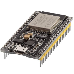
① ESP32 NodeMCU (WROOM-32 기반 표준 보드)
특징: 가장 대중적이며 표준적인 형태다. 양옆으로 넉넉한 입출력 핀이 나열되어 브레드보드에 직접 실장 하여 회로를 테스트하기에 적합하다. 최근 출고되는 제품들은 USB Type-C 단자를 표준으로 채택하고 있다.
주요 용도: 입문자용 하드웨어 학습, 홈 어시스턴트(Home Assistant) 연동 온습도 및 미세먼지 측정기, 범용 스마트 가전 제어기.
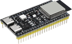
② ESP32-S3 및 ESP32-C3 개발 보드 (고성능/차세대 표준형)
특징: 외형은 기존 NodeMCU와 유사하나 내부 칩셋이 업그레이드된 형태다. 듀얼 USB 포트를 탑재한 S3 보드나 오픈소스 RISC-V 기반인 C3 보드가 속한다.
주요 용도: 고해상도 그래픽 처리, 디스플레이 연동 장치, 암호화 통신 노드.
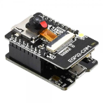
③ ESP32-CAM (카메라 일체형 보드)
특징: 오리지널 ESP32 칩셋에 OV2640 소형 카메라 모듈 슬롯과 데이터 저장을 위한 MicroSD 카드 슬롯을 통합한 특수 목적 보드다. 매우 저렴하지만 사용 가능한 잔여 핀(GPIO) 수가 적다는 제약이 있다.
주요 용도: DIY 무선 CCTV 홈 캠, 현관문 실시간 스트리밍 카메라, 엣지 컴퓨팅 기반의 간이 안면 인식 장치.
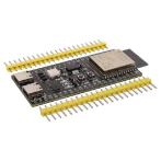
④ ESP32 SuperMini 시리즈 (초소형 폼팩터)
특징: 엄지손가락 한 마디 미만의 극단적인 소형화를 이룬 보드다 ESP32 C3 vs S3. 입출력 핀의 수는 적으나 공간 효율성이 극대화되어 시제품 및 완제품 내부에 매립하기 최적의 조건을 지닌다.
주요 용도: 웨어러블 디바이스, 벽면 스위치 박스 매립형 무선 릴레이 모듈, 소형 드론 및 RC카 제어 기판
4. ESP32를 활용한 대표적인 IoT 프로젝트 예시
ESP32는 강력한 하드웨어 스펙을 바탕으로 다양한 산업 및 개인 프로젝트에 투입된다.
🏡 스마트 홈 자동화 시스템 (Home Automation)
ESP32의 Wi-Fi 기능을 활용하여 기성 가전기기를 스마트 가전으로 리모델링할 수 있다. 센서로부터 획득한 데이터를 기반으로 MQTT 프로토콜을 통해 홈 서버와 통신하며, 시스템의 말단에서 릴레이(Relay) 모듈을 제어하는 핵심 단말기 역할을 수행한다
📈 실시간 데이터 전광판 및 크립토 티커 (Crypto Ticker)
네트워크에 상시 접속하여 실시간 API 데이터를 파싱하는 웹 클라이언트 구현이 가능하다. 날씨 정보 API를 받아오는 데스크톱 스마트 시계나, 주식 및 가상화폐의 실시간 시세를 소형 TFT LCD에 출력하는 '크립토 티커' 제작이 대표적인 사례다 ESP32 C3 vs S3.
💡 결론 및 프로젝트별 최종 선택 가이드
본인의 프로젝트 목적에 따라 최적의 칩셋을 매칭하는 기준은 다음과 같이 요약할 수 있다.
하드웨어 제어 입문 및 가장 방대한 레퍼런스가 필요한 경우: 👉 검증된 오리지널 ESP32 NodeMCU (WROOM-32)를 선택하는 것이 가장 안전하다
단가 절감과 소형화가 최우선이며, 단순 센서 데이터 수집이 목적인 경우: 👉 ESP32-C3 SuperMini 보드가 비용 대비 최고의 효율을 제공한다 ESP32-C3 SuperMini 개발 보드 ESP32 C3 S3 C6 H2 슈퍼 미니 WiFi IOT 보드 기반 MicroPython Arduino 호환.
카메라 스트리밍, AI 연산, 고해상도 그래픽 출력이 요구되는 경우: 👉 고성능 듀얼 코어와 벡터 가속을 지원하는 ESP32-S3 도입이 필수적이다
Matter 표준 등 차세대 스마트홈 생태계 연동을 염두에 둔 경우: 👉 Zigbee와 Thread 통신을 지원하는 ESP32-C6 기반 보드를 선택해야 한다 esp32-c6과 s3 차이점 - Girin.
ESP32는 아두이노 IDE를 완벽히 지원하므로 진입 장벽이 낮으면서도, 그 확장성은 무궁무진하다. 본인의 설계 목적과 예산에 부합하는 올바른 라인업을 선택하여 완성도 높은 IoT 프로젝트를 구축할 수 있다.
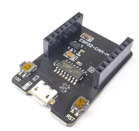
ESP32-CAM은 소형카메라에 WIFI까지 내장한 ESP32 프로세서를 탑재하고도 5~6$라는 저렴한 비용으로 판매되고 있기 때문에 매우 인기가 좋다. 그런데 하나 불편한 점이 USB 회로가 내장되어 있지 않아 PC에서 제작한 프로그램을 업로드하기가 번거롭다는 것이었는데 여기 소개하는 Adapter보드를 이용하면 편리하게 프로그램에 활용할 수 있다.
1. ESP32-CAM Adapter보드 소개
ESP32-CAM Adapter보드는 CH340칩을 이용한 USB Inferface 보드로서 일반 어두 이노 나노 보드처럼 PC에서 제작한 프로그램을 업로드할 수 있고 ESP32-CAM보듈에 전원을 공급할 수 있으며 ESP32-CAM 모듈을 꽃을 수 있는 소켓이 내장되어 있다.
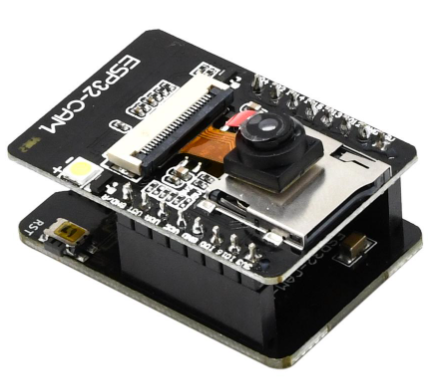
ESP32-CAM Adapter보드 위에 ESP32-CAM 모듈을 꽂으면 아래와 같은 모양이 되어 일반적인 아두이노 모듈을 가지고 프로그램하는 것과 비슷한 방식으로 PC에 USB연결 사용할 수 있게 된다.
2. ESP32-CAM Adapter보드 구성
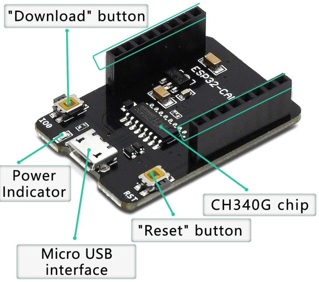
아래와 같이 Power 표시등과 Reset버튼,Download버튼이 내장되어 있다.
3. ESP32-CAM Adapter보드 사용법
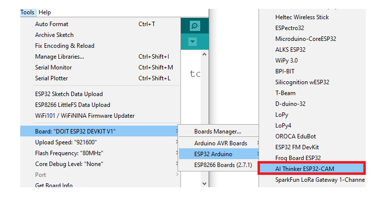
1) 아두이노 IDE에서 보드를 AI-Thinker ESP32-CAM로 선택하여 지정한다.
2) ESP32-CAM영 프로그램을 제작한 후 Upload를 실행한 후 대기 중일 때 Adapter 보드의 Download버튼을 한번 눌러주면 LEDrk 깜박깜박하며 프로그램이 ESP32-CAM모듈에 업로드된다. 프로그램이 업로드된 이후에는 Adapter 보드를 분리시키고 ESP32-CAM모듈에 전원을 공급하면 정상 작동된다.
(*** 만약 버튼을 눌러도 다운로드가 실행되지 않고 다음과 같은 메세지가 나오면 ESP32-CAM본체의 RESET버튼을 먼저 한번 눌러 주면 정상처리 된다
"fatal error occurred: Failed to connect to ESP32: Timed out waiting for packet header" )
4. AI-Thinker ESP32-CAM 보드가 표시되지 않을 경우
ESP32관련 모듈들이 최근 상태로 설치되어 있지 않은 상태이므로 다음 과정으로 ESP32 Addon모듈들을 설치해 주면 된다.
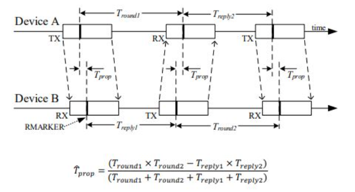
DWM1000을 이용한 거리측정 방법은 타임스탬프를 포함하는 통신 패킷을 다른 모듈로 전송하고 응답되는 시간을 측정하여 시각차이를 측정하여 거리를 계산하는 방식이다.
2. 거리측정 샘플프로그램
2-1 앵커 모듈용(신호응답)
/*
 * MIT License
 *
 * Copyright (c) 2018 Michele Biondi, Andrea Salvatori
 *
 * Permission is hereby granted, free of charge, to any person obtaining a copy
 * of this software and associated documentation files (the "Software"), to deal
 * in the Software without restriction, including without limitation the rights
 * to use, copy, modify, merge, publish, distribute, sublicense, and/or sell
 * copies of the Software, and to permit persons to whom the Software is
 * furnished to do so, subject to the following conditions:
 *
 * The above copyright notice and this permission notice shall be included in all
 * copies or substantial portions of the Software.
 *
 * THE SOFTWARE IS PROVIDED "AS IS", WITHOUT WARRANTY OF ANY KIND, EXPRESS OR
 * IMPLIED, INCLUDING BUT NOT LIMITED TO THE WARRANTIES OF MERCHANTABILITY,
 * FITNESS FOR A PARTICULAR PURPOSE AND NONINFRINGEMENT. IN NO EVENT SHALL THE
 * AUTHORS OR COPYRIGHT HOLDERS BE LIABLE FOR ANY CLAIM, DAMAGES OR OTHER
 * LIABILITY, WHETHER IN AN ACTION OF CONTRACT, TORT OR OTHERWISE, ARISING FROM,
 * OUT OF OR IN CONNECTION WITH THE SOFTWARE OR THE USE OR OTHER DEALINGS IN THE
 * SOFTWARE.
*/

/*
 * Copyright (c) 2015 by Thomas Trojer <thomas@trojer.net>
 * Decawave DW1000 library for arduino.
 *
 * Licensed under the Apache License, Version 2.0 (the "License");
 * you may not use this file except in compliance with the License.
 * You may obtain a copy of the License at
 *
 *     http://www.apache.org/licenses/LICENSE-2.0
 *
 * Unless required by applicable law or agreed to in writing, software
 * distributed under the License is distributed on an "AS IS" BASIS,
 * WITHOUT WARRANTIES OR CONDITIONS OF ANY KIND, either express or implied.
 * See the License for the specific language governing permissions and
 * limitations under the License.
 *
 * @file RangingTag.ino
 * Use this to test two-way ranging functionality with two DW1000Ng:: This is
 * the tag component's code which polls for range computation. Addressing and
 * frame filtering is currently done in a custom way, as no MAC features are
 * implemented yet.
 *
 * Complements the "RangingAnchor" example sketch.
 *
 * @todo
 *  - use enum instead of define
 *  - move strings to flash (less RAM consumption)
 */

#include <DW1000Ng.hpp>
#include <DW1000NgUtils.hpp>
#include <DW1000NgTime.hpp>
#include <DW1000NgConstants.hpp>
/*
// connection pins
const uint8_t PIN_RST = 9; // reset pin
const uint8_t PIN_IRQ = 2; // irq pin
const uint8_t PIN_SS = SS; // spi select pin
*/

const uint8_t PIN_SCK = 18;
const uint8_t PIN_MOSI = 23;
const uint8_t PIN_MISO = 19;
const uint8_t PIN_SS = 2;
const uint8_t PIN_RST = 15;
const uint8_t PIN_IRQ = 5;
// messages used in the ranging protocol
// TODO replace by enum
#define POLL 0
#define POLL_ACK 1
#define RANGE 2
#define RANGE_REPORT 3
#define RANGE_FAILED 255
// message flow state
volatile byte expectedMsgId = POLL_ACK;
// message sent/received state
volatile boolean sentAck = false;
volatile boolean receivedAck = false;
// timestamps to remember
uint64_t timePollSent;
uint64_t timePollAckReceived;
uint64_t timeRangeSent;
// data buffer
#define LEN_DATA 16
byte data[LEN_DATA];
// watchdog and reset period
uint32_t lastActivity;
uint32_t resetPeriod = 250;
// reply times (same on both sides for symm. ranging)
uint16_t replyDelayTimeUS = 3000;

device_configuration_t DEFAULT_CONFIG = {
    false,
    true,
    true,
    true,
    false,
    SFDMode::STANDARD_SFD,
    Channel::CHANNEL_5,
    DataRate::RATE_850KBPS,
    PulseFrequency::FREQ_16MHZ,
    PreambleLength::LEN_256,
    PreambleCode::CODE_3
};

interrupt_configuration_t DEFAULT_INTERRUPT_CONFIG = {
    true,
    true,
    true,
    false,
    true
};

void setup() {
    // DEBUG monitoring
    Serial.begin(115200);
    Serial.println(F("### DW1000Ng-arduino-ranging-tag ###"));
    // initialize the driver
    DW1000Ng::initialize(PIN_SS, PIN_IRQ, PIN_RST);
    Serial.println("DW1000Ng initialized ...");
    // general configuration
    DW1000Ng::applyConfiguration(DEFAULT_CONFIG);
	DW1000Ng::applyInterruptConfiguration(DEFAULT_INTERRUPT_CONFIG);

    DW1000Ng::setNetworkId(10);

    DW1000Ng::setAntennaDelay(16436);

    Serial.println(F("Committed configuration ..."));
    // DEBUG chip info and registers pretty printed
    char msg[128];
    DW1000Ng::getPrintableDeviceIdentifier(msg);
    Serial.print("Device ID: "); Serial.println(msg);
    DW1000Ng::getPrintableExtendedUniqueIdentifier(msg);
    Serial.print("Unique ID: "); Serial.println(msg);
    DW1000Ng::getPrintableNetworkIdAndShortAddress(msg);
    Serial.print("Network ID & Device Address: "); Serial.println(msg);
    DW1000Ng::getPrintableDeviceMode(msg);
    Serial.print("Device mode: "); Serial.println(msg);
    // attach callback for (successfully) sent and received messages
    DW1000Ng::attachSentHandler(handleSent);
    DW1000Ng::attachReceivedHandler(handleReceived);
    // anchor starts by transmitting a POLL message
    transmitPoll();
    noteActivity();
}

void noteActivity() {
    // update activity timestamp, so that we do not reach "resetPeriod"
    lastActivity = millis();
}

void resetInactive() {
    // tag sends POLL and listens for POLL_ACK
    expectedMsgId = POLL_ACK;
    DW1000Ng::forceTRxOff();
    transmitPoll();
    noteActivity();
}

void handleSent() {
    // status change on sent success
    sentAck = true;
}

void handleReceived() {
    // status change on received success
    receivedAck = true;
}

void transmitPoll() {
    data[0] = POLL;
    DW1000Ng::setTransmitData(data, LEN_DATA);
    DW1000Ng::startTransmit();
}

void transmitRange() {
    data[0] = RANGE;

    /* Calculation of future time */
    byte futureTimeBytes[LENGTH_TIMESTAMP];

	timeRangeSent = DW1000Ng::getSystemTimestamp();
	timeRangeSent += DW1000NgTime::microsecondsToUWBTime(replyDelayTimeUS);
    DW1000NgUtils::writeValueToBytes(futureTimeBytes, timeRangeSent, LENGTH_TIMESTAMP);
    DW1000Ng::setDelayedTRX(futureTimeBytes);
    timeRangeSent += DW1000Ng::getTxAntennaDelay();

    DW1000NgUtils::writeValueToBytes(data + 1, timePollSent, LENGTH_TIMESTAMP);
    DW1000NgUtils::writeValueToBytes(data + 6, timePollAckReceived, LENGTH_TIMESTAMP);
    DW1000NgUtils::writeValueToBytes(data + 11, timeRangeSent, LENGTH_TIMESTAMP);
    DW1000Ng::setTransmitData(data, LEN_DATA);
    DW1000Ng::startTransmit(TransmitMode::DELAYED);
    //Serial.print("Expect RANGE to be sent @ "); Serial.println(timeRangeSent.getAsFloat());
}

void loop() {
    if (!sentAck && !receivedAck) {
        // check if inactive
        if (millis() - lastActivity > resetPeriod) {
            resetInactive();
        }
        return;
    }
    // continue on any success confirmation
    if (sentAck) {
        sentAck = false;
        DW1000Ng::startReceive();
    }
    if (receivedAck) {
        receivedAck = false;
        // get message and parse
        DW1000Ng::getReceivedData(data, LEN_DATA);
        byte msgId = data[0];
        if (msgId != expectedMsgId) {
            // unexpected message, start over again
            //Serial.print("Received wrong message # "); Serial.println(msgId);
            expectedMsgId = POLL_ACK;
            transmitPoll();
            return;
        }
        if (msgId == POLL_ACK) {
            timePollSent = DW1000Ng::getTransmitTimestamp();
            timePollAckReceived = DW1000Ng::getReceiveTimestamp();
            expectedMsgId = RANGE_REPORT;
            transmitRange();
            noteActivity();
        } else if (msgId == RANGE_REPORT) {
            expectedMsgId = POLL_ACK;
            float curRange;
            memcpy(&curRange, data + 1, 4);
            transmitPoll();
            noteActivity();
        } else if (msgId == RANGE_FAILED) {
            expectedMsgId = POLL_ACK;
            transmitPoll();
            noteActivity();
        }
    }
}
2-2 태그모듈용(거리계산 출력)
/*
 * MIT License
 *
 * Copyright (c) 2018 Michele Biondi, Andrea Salvatori
 *
 * Permission is hereby granted, free of charge, to any person obtaining a copy
 * of this software and associated documentation files (the "Software"), to deal
 * in the Software without restriction, including without limitation the rights
 * to use, copy, modify, merge, publish, distribute, sublicense, and/or sell
 * copies of the Software, and to permit persons to whom the Software is
 * furnished to do so, subject to the following conditions:
 *
 * The above copyright notice and this permission notice shall be included in all
 * copies or substantial portions of the Software.
 *
 * THE SOFTWARE IS PROVIDED "AS IS", WITHOUT WARRANTY OF ANY KIND, EXPRESS OR
 * IMPLIED, INCLUDING BUT NOT LIMITED TO THE WARRANTIES OF MERCHANTABILITY,
 * FITNESS FOR A PARTICULAR PURPOSE AND NONINFRINGEMENT. IN NO EVENT SHALL THE
 * AUTHORS OR COPYRIGHT HOLDERS BE LIABLE FOR ANY CLAIM, DAMAGES OR OTHER
 * LIABILITY, WHETHER IN AN ACTION OF CONTRACT, TORT OR OTHERWISE, ARISING FROM,
 * OUT OF OR IN CONNECTION WITH THE SOFTWARE OR THE USE OR OTHER DEALINGS IN THE
 * SOFTWARE.
*/

/*
 * Copyright (c) 2015 by Thomas Trojer <thomas@trojer.net>
 * Decawave DW1000 library for arduino.
 *
 * Licensed under the Apache License, Version 2.0 (the "License");
 * you may not use this file except in compliance with the License.
 * You may obtain a copy of the License at
 *
 *     http://www.apache.org/licenses/LICENSE-2.0
 *
 * Unless required by applicable law or agreed to in writing, software
 * distributed under the License is distributed on an "AS IS" BASIS,
 * WITHOUT WARRANTIES OR CONDITIONS OF ANY KIND, either express or implied.
 * See the License for the specific language governing permissions and
 * limitations under the License.
 *
 * @file RangingAnchor.ino
 * Use this to test two-way ranging functionality with two
 * DW1000Ng:: This is the anchor component's code which computes range after
 * exchanging some messages. Addressing and frame filtering is currently done
 * in a custom way, as no MAC features are implemented yet.
 *
 * Complements the "RangingTag" example sketch.
 *
 * @todo
 *  - weighted average of ranging results based on signal quality
 *  - use enum instead of define
 *  - move strings to flash (less RAM consumption)
 */

#include <DW1000Ng.hpp>
#include <DW1000NgUtils.hpp>
#include <DW1000NgRanging.hpp>
/*
// connection pins
const uint8_t PIN_RST = 9; // reset pin
const uint8_t PIN_IRQ = 2; // irq pin
const uint8_t PIN_SS = SS; // spi select pin
*/

const uint8_t PIN_SCK = 18;
const uint8_t PIN_MOSI = 23;
const uint8_t PIN_MISO = 19;
const uint8_t PIN_SS = 2;
const uint8_t PIN_RST = 15;
const uint8_t PIN_IRQ = 5;
// messages used in the ranging protocol
// TODO replace by enum
#define POLL 0
#define POLL_ACK 1
#define RANGE 2
#define RANGE_REPORT 3
#define RANGE_FAILED 255
// message flow state
volatile byte expectedMsgId = POLL;
// message sent/received state
volatile boolean sentAck = false;
volatile boolean receivedAck = false;
// protocol error state
boolean protocolFailed = false;
// timestamps to remember
uint64_t timePollSent;
uint64_t timePollReceived;
uint64_t timePollAckSent;
uint64_t timePollAckReceived;
uint64_t timeRangeSent;
uint64_t timeRangeReceived;

uint64_t timeComputedRange;
// last computed range/time
// data buffer
#define LEN_DATA 16
byte data[LEN_DATA];
// watchdog and reset period
uint32_t lastActivity;
uint32_t resetPeriod = 250;
// reply times (same on both sides for symm. ranging)
uint16_t replyDelayTimeUS = 3000;
// ranging counter (per second)
uint16_t successRangingCount = 0;
uint32_t rangingCountPeriod = 0;
float samplingRate = 0;

device_configuration_t DEFAULT_CONFIG = {
    false,
    true,
    true,
    true,
    false,
    SFDMode::STANDARD_SFD,
    Channel::CHANNEL_5,
    DataRate::RATE_850KBPS,
    PulseFrequency::FREQ_16MHZ,
    PreambleLength::LEN_256,
    PreambleCode::CODE_3
};

interrupt_configuration_t DEFAULT_INTERRUPT_CONFIG = {
    true,
    true,
    true,
    false,
    true
};

void setup() {
    // DEBUG monitoring
    Serial.begin(115200);
    delay(1000);
    Serial.println(F("### DW1000Ng-arduino-ranging-anchor ###"));
    // initialize the driver
    DW1000Ng::initialize(PIN_SS, PIN_IRQ, PIN_RST);
    Serial.println(F("DW1000Ng initialized ..."));
    // general configuration
    DW1000Ng::applyConfiguration(DEFAULT_CONFIG);
	DW1000Ng::applyInterruptConfiguration(DEFAULT_INTERRUPT_CONFIG);

    DW1000Ng::setDeviceAddress(1);

    DW1000Ng::setAntennaDelay(16436);

    Serial.println(F("Committed configuration ..."));
    // DEBUG chip info and registers pretty printed
    char msg[128];
    DW1000Ng::getPrintableDeviceIdentifier(msg);
    Serial.print("Device ID: "); Serial.println(msg);
    DW1000Ng::getPrintableExtendedUniqueIdentifier(msg);
    Serial.print("Unique ID: "); Serial.println(msg);
    DW1000Ng::getPrintableNetworkIdAndShortAddress(msg);
    Serial.print("Network ID & Device Address: "); Serial.println(msg);
    DW1000Ng::getPrintableDeviceMode(msg);
    Serial.print("Device mode: "); Serial.println(msg);
    // attach callback for (successfully) sent and received messages
    DW1000Ng::attachSentHandler(handleSent);
    DW1000Ng::attachReceivedHandler(handleReceived);
    // anchor starts in receiving mode, awaiting a ranging poll message

    receiver();
    noteActivity();
    // for first time ranging frequency computation
    rangingCountPeriod = millis();
}

void noteActivity() {
    // update activity timestamp, so that we do not reach "resetPeriod"
    lastActivity = millis();
}

void resetInactive() {
    // anchor listens for POLL
    expectedMsgId = POLL;
    receiver();
    noteActivity();
}

void handleSent() {
    // status change on sent success
    sentAck = true;
}

void handleReceived() {
    // status change on received success
    receivedAck = true;
}

void transmitPollAck() {
    data[0] = POLL_ACK;
    DW1000Ng::setTransmitData(data, LEN_DATA);
    DW1000Ng::startTransmit();
}

void transmitRangeReport(float curRange) {
    data[0] = RANGE_REPORT;
    // write final ranging result
    memcpy(data + 1, &curRange, 4);
    DW1000Ng::setTransmitData(data, LEN_DATA);
    DW1000Ng::startTransmit();
}

void transmitRangeFailed() {
    data[0] = RANGE_FAILED;
    DW1000Ng::setTransmitData(data, LEN_DATA);
    DW1000Ng::startTransmit();
}

void receiver() {
    DW1000Ng::forceTRxOff();
    // so we don't need to restart the receiver manually
    DW1000Ng::startReceive();
}

void loop() {
    int32_t curMillis = millis();
    if (!sentAck && !receivedAck) {
        // check if inactive
        if (curMillis - lastActivity > resetPeriod) {
            resetInactive();
        }
        return;
    }
    // continue on any success confirmation
    if (sentAck) {
        sentAck = false;
        byte msgId = data[0];
        if (msgId == POLL_ACK) {
            timePollAckSent = DW1000Ng::getTransmitTimestamp();
            noteActivity();
        }
        DW1000Ng::startReceive();
    }
    if (receivedAck) {
        receivedAck = false;
        // get message and parse
        DW1000Ng::getReceivedData(data, LEN_DATA);
        byte msgId = data[0];
        if (msgId != expectedMsgId) {
            // unexpected message, start over again (except if already POLL)
            protocolFailed = true;
        }
        if (msgId == POLL) {
            // on POLL we (re-)start, so no protocol failure
            protocolFailed = false;
            timePollReceived = DW1000Ng::getReceiveTimestamp();
            expectedMsgId = RANGE;
            transmitPollAck();
            noteActivity();
        }
        else if (msgId == RANGE) {
            timeRangeReceived = DW1000Ng::getReceiveTimestamp();
            expectedMsgId = POLL;
            if (!protocolFailed) {
                timePollSent = DW1000NgUtils::bytesAsValue(data + 1, LENGTH_TIMESTAMP);
                timePollAckReceived = DW1000NgUtils::bytesAsValue(data + 6, LENGTH_TIMESTAMP);
                timeRangeSent = DW1000NgUtils::bytesAsValue(data + 11, LENGTH_TIMESTAMP);
                // (re-)compute range as two-way ranging is done
                double distance = DW1000NgRanging::computeRangeAsymmetric(timePollSent,
                                                            timePollReceived,
                                                            timePollAckSent,
                                                            timePollAckReceived,
                                                            timeRangeSent,
                                                            timeRangeReceived);
                /* Apply simple bias correction */
                distance = DW1000NgRanging::correctRange(distance);

                String rangeString = "Range: "; rangeString += distance; rangeString += " m";
                rangeString += "\t RX power: "; rangeString += DW1000Ng::getReceivePower(); rangeString += " dBm";
                rangeString += "\t Sampling: "; rangeString += samplingRate; rangeString += " Hz";
                Serial.println(rangeString);
                //Serial.print("FP power is [dBm]: "); Serial.print(DW1000Ng::getFirstPathPower());
                //Serial.print("RX power is [dBm]: "); Serial.println(DW1000Ng::getReceivePower());
                //Serial.print("Receive quality: "); Serial.println(DW1000Ng::getReceiveQuality());
                // update sampling rate (each second)
                transmitRangeReport(distance * DISTANCE_OF_RADIO_INV);
                successRangingCount++;
                if (curMillis - rangingCountPeriod > 1000) {
                    samplingRate = (1000.0f * successRangingCount) / (curMillis - rangingCountPeriod);
                    rangingCountPeriod = curMillis;
                    successRangingCount = 0;
                }
            }
            else {
                transmitRangeFailed();
            }

            noteActivity();
        }
    }
}
3. 테스트결과
- 비교적 안정적으로 거리 측정이 되고 거리 이동에 따라 실시간으로 변경되는 등 상당히 정확히 반응했지만 거의 근접했을 떄 음수값이 나오는 등 이상 현상이 발생된다. 모듈별 또는 MCU 기종에 따라 변화되는 내용을 Calibration 작업해 주여야 할 것을 보인다.
-다른 거리측정 방식에 비해 장점은 비교적 정확한 거리 측정이 가능하다는 점 이외에도 중간 장애물이 있어도 사용 가능하다는 것이다. 초음파,레이저에 의한 거리측정의 경우 중간 장애물이 있으면 장애물에서 반사되어 버리기 때문에 중간 장애물과의 거리가 측정되어 버리지만 UWB방식의 거리측정은 두 모듈간 패킷을 주고 받는 시간간격을 측정하여 계산하는 방식이기 때문에 중간장애물이 있어도 크게 영향을 받지 않는다. 실제로 한 모듈은 책상위 또 다른 모듈은 책상아래에 놓고 움직여 보아도 원만하게 거리 변동이 추적된다.
-제조사에서는 PCB내장안테나 만으로도 40m까지 측정가능하다고 하나 약간의 장매울에도 신호감도가 약해지는 것을 볼때 이것이 가능할 것인지는 의문이다. 다른 사용자들의 실험에 의하면 내장안테나 모델일 경우 탁트인 환경에서도 10미터 내외가 한계라는 것을 보아 실무에서 활용할 때에는 최소한 앵커 모듈에는 고출력 외장안테나를 사용하는 방식이 되어야 할 것으로 보인다.